orGUI Geometry
orGUI was developed for high-energy surface X-ray diffraction (HESXRD) and transmission surface diffraction workflows where a large, stationary 2D detector records many reciprocal-space features during a sample rotation. The geometry combines a pyFAI-style detector description with a surface-diffraction diffractometer convention based on Busing and Levy and on Lohmeier and Vlieg.
Reference Frames
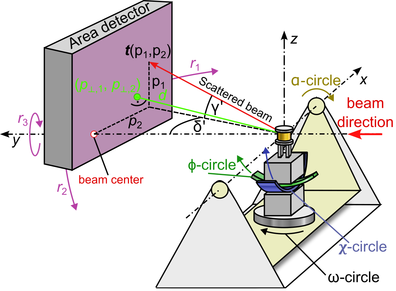
The diffractometer origin is the sample position. In the laboratory frame,
y points along the incident beam, x points perpendicular to the beam in
the radial direction, and z completes the right-handed frame. The azimuth
parameter in the machine settings rotates the diffractometer frame around the
incident beam direction; for an azimuth of 90 degrees, z points upward.
The sample is positioned by the alpha, omega, chi, and phi
circles. orGUI follows the Lohmeier and Vlieg angle convention for the shared
axes, but uses a phi circle around the x axis. The theta scan axis used
at some beamlines is mapped to the internal omega angle as
\(\theta = -\omega\).
Detector Geometry
The detector model follows the pyFAI geometry convention. A detector pixel is described relative to the point of normal incidence, the sample-detector distance, and the detector rotations. The detector calibration therefore provides the mapping between detector pixel coordinates and the scattering angles observed by the area detector.
For surface diffraction, orGUI converts the detector scattering direction into
the in-plane and out-of-plane detector angles delta and gamma. The
conversion accounts for the azimuthal reference direction of the surface normal
and for the current alpha setting. These angles are then used together with
the sample-circle angles in the reciprocal-space calculation.
Diffraction Equation
The reciprocal lattice vector is written in reciprocal lattice coordinates as
\(\vec{H} = (h, k, l)^T\). The crystal B matrix converts this vector
from reciprocal lattice units to a Cartesian reciprocal-space vector, and the
orientation matrix U attaches the crystal to the inner sample-circle frame.
In orGUI notation, the sample rotations transform the crystal vector into the
alpha frame. The momentum transfer vector is calculated from the incoming
and outgoing wavevectors in the same frame. The diffraction condition is met
when the transformed reciprocal lattice vector equals the measured momentum
transfer vector.
For crystal truncation rod and arbitrary line integration, the reciprocal-space trajectory is described as
where \(\vec{H}_0\) and \(\vec{H}_1\) are vectors in reciprocal lattice units. orGUI calculates the intersections of this line with the Ewald sphere and converts the corresponding detector angles back to detector pixel coordinates.
Further Reading
The implemented geometry is summarized in chapter 5, especially section 5.3, of Timo Fuchs’ dissertation. The angle convention builds on:
Busing and H. A. Levy, Acta Crystallographica 22, 457-464 (1967).
M. Lohmeier and E. Vlieg, Journal of Applied Crystallography 26, 706-716 (1993), https://doi.org/10.1107/S0021889893004868.